Room EQ Wizard study
Having done some IB designs for the Venom 15inch drivers, my need for bass was awakened once more...
To evaluate potential locations for an IB installation, I downloaded the
Room EQ Wizard
from Home Theater Shack.
Note - You will need to become a member (free) before you can access the downloads
The software allows a frequency sweep to be sent to the sub whilst monitoring the response via a microphone.
I used the microphone built into the Radio Shack SPL meter that I've been using for ages.
By putting the sub in the listening position and moving the mic to potential subwoofer locations,
the effect of room nodes can be seen.
The software also knows about several different equalisers such as the
Behringer Feedback destroyer (BFD).
It can auto-model the effects of filters and show the optimised response.
The filter settings can then be uploaded to the BFD via your MIDI port.
This page is an example of how Room EQ Wizard can be used to make informed
choices about subwoofer location
I get on well with my neighbors, and was concerned that the traditional above-ceiling or below-floor locations would require a lot of soundproofing to be viable.
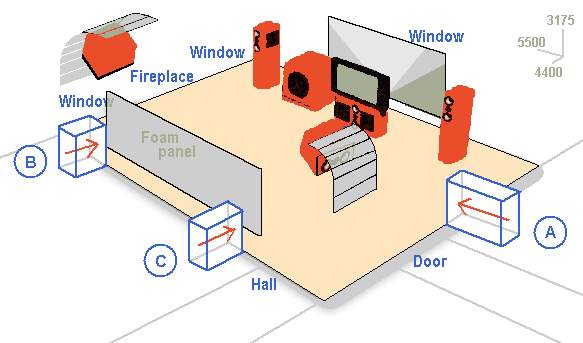
This just left adjacent rooms as potential IB sites, as shown below.
Location A would be the most convenient, whilst
Locations B and C may have potential phase problems.
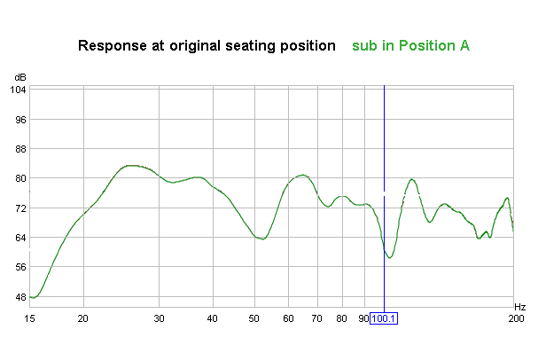
The following graph shows the sub at Location A at the side of the room.
The huge dip around 50hz is the result of a room node activated across the room from side to side.
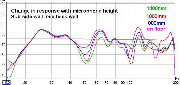
I had read that the height of the microphone can change the reading.
Hoping that this might account for the hole, I repeated the test with four different microphone heights.
As can be seen, the results do change, but that hole is still there!
This would suggest that Location A is unsuitable for a subwoofer.
Next we have Locations B and C
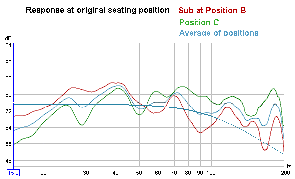
The two positions vary, but the average response is encouraging, showing only minor dips and peaks.
It seems that Locations B and C produce a better result than
that obtained at Location A
The new seating position is a result of rearranging the room by 180 degrees as shown in this drawing
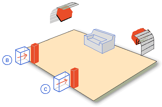
This arrangement puts the mains next to Locations B and C
thus solving the integration problem.
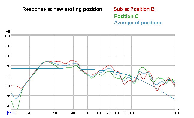
The next graph shows the response at the
new seating position.
Again, both sub locations were tested, and the average response is also shown.
Conclusion
A pair of subs mounted at Locations B and C
will produce far better results than what could be achieved at Location A.
The backwave will be contained in an adjacent room 3.9m wide * 3.9, same height, for a volume of around 48 m^3.
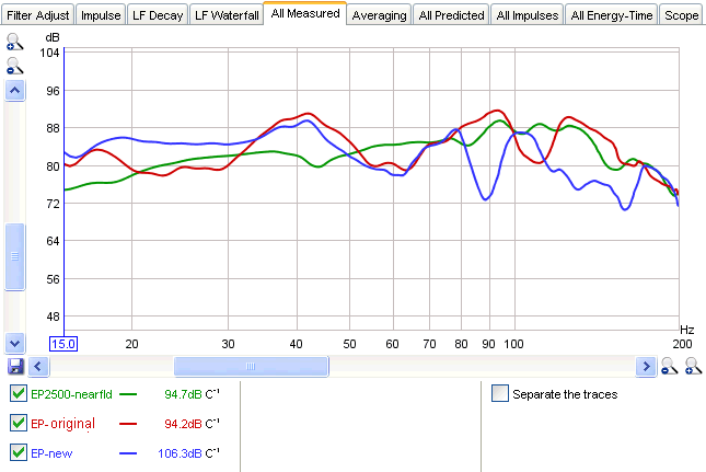
The IB has now been built - here's what was actually measured after installation
The flatter response is a result of moving to an EP2500 amp which doesn't have the limitations of the Jaycar unit used above.
Green is a nearfield measurement from within one of the manifolds
Red is the original seating position.
Blue is the new position after the room was rearranged. The low-end lift provided by room gain can be seen here.
Either position can be successfully tamed with the BFD.
